widgeo.net

Translate


Basic Components

Welcome

SEO Reports for basicelectronicomponent.blogspot.com
Memaparkan catatan dengan label diode. Papar semua catatan

Sabtu, 25 Mei 2013

Relays


see also : Switches | Diodes 


Relay, photograph © Rapid Electronics
Relays
working relay
Relay showing coil and switch contacts
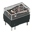
A relay is an electrically operated switch. Current flowing through the coil of the relay creates a magnetic field which attracts a lever and changes the switch contacts. The coil current can be on or off so relays have two switch positions and most have double throw(changeover) switch contacts as shown in the diagram.
Relays allow one circuit to switch a second circuit which can be completely separate from the first. For example a low voltage battery circuit can use a relay to switch a 230V AC mains circuit. There is no electrical connection inside the relay between the two circuits, the link is magnetic and mechanical.
The coil of a relay passes a relatively large current, typically 30mA for a 12V relay, but it can be as much as 100mA for relays designed to operate from lower voltages. Most ICs (chips) cannot provide this current and a transistor is usually used to amplify the small IC current to the larger value required for the relay coil. The maximum output current for the popular 555 timer IC is 200mA so these devices can supply relay coils directly without amplification.
Relays are usuallly SPDT or DPDT but they can have many more sets of switch contacts, for example relays with 4 sets of changeover contacts are readily available. For further information about switch contacts and the terms used to describe them please see the page onswitches.
Most relays are designed for PCB mounting but you can solder wires directly to the pins providing you take care to avoid melting the plastic case of the relay.
The supplier's catalogue or website should show the relay's connections. The coil will be obvious and it may be connected either way round. Relay coils produce brief high voltage 'spikes' when they are switched off and this can destroy transistors and ICs in the circuit. To prevent damage you must connect a protection diode across the relay coil.
The animated picture shows a working relay with its coil and switch contacts. You can see a lever on the left being attracted by magnetism when the coil is switched on. This lever moves the switch contacts. There is one set of contacts (SPDT) in the foreground and another behind them, making the relay DPDT.

The relay's switch connections are usually labelled COM, NC and NO:
  • COM = Common, always connect to this, it is the moving part of the switch.
  • NC = Normally Closed, COM is connected to this when the relay coil is off.
  • NO = Normally Open, COM is connected to this when the relay coil is on.
  • Connect to COM and NO if you want the switched circuit to be on when the relay coil is on.
  • Connect to COM and NC if you want the switched circuit to be on when the relay coil is off.

Choosing a relay

You need to consider several features when choosing a relay:
  1. Physical size and pin arrangement
    If you are choosing a relay for an existing PCB you will need to ensure that its dimensions and pin arrangement are suitable. You should find this information in the supplier's catalogue or on their website.
  2. Coil voltage
    The relay's coil voltage rating and resistance must suit the circuit powering the relay coil. Many relays have a coil rated for a 12V supply but 5V and 24V relays are also readily available. Some relays operate perfectly well with a supply voltage which is a little lower than their rated value.
  3. Coil resistance
    The circuit must be able to supply the current required by the relay coil. You can use Ohm's law to calculate the current:
    Relay coil current   =   supply voltage 
      coil resistance
    For example: A 12V supply relay with a coil resistance of 400 passes a current of 30mA. This is OK for a 555 timer IC (maximum output current 200mA), but it is too much for most ICs and they will require a transistor to amplify the current.
  4. Switch ratings (voltage and current)
    The relay's switch contacts must be suitable for the circuit they are to control. You will need to check the voltage and current ratings. Note that the voltage rating is usually higher for AC, for example: "5A at 24V DC or 125V AC".
  5. Switch contact arrangement (SPDT, DPDT etc)
    Most relays are SPDT or DPDT which are often described as "single pole changeover" (SPCO) or "double pole changeover" (DPCO). For further information please see the page on switches.

Protection diodes for relays

Protection diode for a relayTransistors and ICs must be protected from the brief high voltage produced when a relay coil is switched off. The diagram shows how a signal diode (eg 1N4148) is connected 'backwards' across the relay coil to provide this protection.
Current flowing through a relay coil creates a magnetic field which collapses suddenly when the current is switched off. The sudden collapse of the magnetic field induces a brief high voltage across the relay coil which is very likely to damage transistors and ICs. The protection diode allows the induced voltage to drive a brief current through the coil (and diode) so the magnetic field dies away quickly rather than instantly. This prevents the induced voltage becoming high enough to cause damage to transistors and ICs. 

Reed relays

Reed Relay, photograph © Rapid Electronics
Reed Relay
Reed relays consist of a coil surrounding a reed switch. Reed switches are normally operated with a magnet, but in a reed relay current flows through the coil to create a magnetic field and close the reed switch.
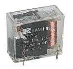
Reed relays generally have higher coil resistances than standard relays (1000ohm for example) and a wide range of supply voltages (9-20V for example). They are capable of switching much more rapidly than standard relays, up to several hundred times per second; but they can only switch low currents (500mA maximum for example).
The reed relay shown in the photograph will plug into a standard 14-pin DIL socket ('IC holder').
For further information about reed switches please see the page on switches

Relays and transistors compared

Like relays, transistors can be used as an electrically operated switch. For switching small DC currents (< 1A) at low voltage they are usually a better choice than a relay. However, transistors cannot switch AC (such as mains electricity) and in simple circuits they are not usually a good choice for switching large currents (> 5A). In these cases a relay will be needed, but note that a low power transistor may still be needed to switch the current for the relay's coil! The main advantages and disadvantages of relays are listed below:

Advantages of relays:
  • Relays can switch AC and DC, transistors can only switch DC.
  • Relays can switch higher voltages than standard transistors.
  • Relays are often a better choice for switching large currents (> 5A).
  • Relays can switch many contacts at once.
Disadvantages of relays:

  • Relays are bulkier than transistors for switching small currents.
  • Relays cannot switch rapidly (except reed relays), transistors can switch many times per second.
  • Relays use more power due to the current flowing through their coil.
  • Relays require more current than many ICs can provide, so a low power transistor may be needed to switch the current for the relay's coil.

Diodes


Signal diodes | Rectifier diodes | Bridge rectifiers | Zener diodes
Also see: LEDs | AC and DC | Power Supplies 


Examples:   Diodes   
Circuit symbol:   Diode circuit symbol 

Function

Diode characteristicDiodes allow electricity to flow in only one direction. The arrow of the circuit symbol shows the direction in which the current can flow. Diodes are the electrical version of a valve and early diodes were actually called valves.

Forward Voltage Drop

Electricity uses up a little energy pushing its way through the diode, rather like a person pushing through a door with a spring. This means that there is a small voltage across a conducting diode, it is called the forward voltage drop and is about 0.7V for all normal diodes which are made from silicon. The forward voltage drop of a diode is almost constant whatever the current passing through the diode so they have a very steep characteristic (current-voltage graph).

Reverse Voltage

When a reverse voltage is applied a perfect diode does not conduct, but all real diodes leak a very tiny current of a few µA or less. This can be ignored in most circuits because it will be very much smaller than the current flowing in the forward direction. However, all diodes have a maximum reverse voltage(usually 50V or more) and if this is exceeded the diode will fail and pass a large current in the reverse direction, this is called breakdown.
Ordinary diodes can be split into two types: Signal diodes which pass small currents of 100mA or less and Rectifier diodes which can pass large currents. In addition there are LEDs (which have their own page) and Zener diodes (at the bottom of this page).


Connecting and soldering

Diode connectionsDiodes must be connected the correct way round, the diagram may be labelled aor + for anode and k or - for cathode (yes, it really is k, not c, for cathode!). The cathode is marked by a line painted on the body. Diodes are labelled with their code in small print, you may need a magnifying glass to read this on small signal diodes!
Small signal diodes can be damaged by heat when soldering, but the risk is small unless you are using a germanium diode (codes beginning OA...) in which case you should use a heat sink clipped to the lead between the joint and the diode body. A standard crocodile clip can be used as a heat sink.
Rectifier diodes are quite robust and no special precautions are needed for soldering them. 


Testing diodes

You can use a multimeter or a simple tester (battery, resistor and LED) to check that a diode conducts in one direction but not the other. A lamp may be used to test a rectifier diode, but do NOT use a lamp to test a signal diode because the large current passed by the lamp will destroy the diode!

Signal diodes (small current)

Signal diodes are used to process information (electrical signals) in circuits, so they are only required to pass small currents of up to 100mA.
General purpose signal diodes such as the 1N4148 are made from silicon and have a forward voltage drop of 0.7V.
Germanium diodes such as the OA90 have a lower forward voltage drop of 0.2V and this makes them suitable to use in radio circuits as detectors which extract the audio signal from the weak radio signal.
For general use, where the size of the forward voltage drop is less important, silicon diodes are better because they are less easily damaged by heat when soldering, they have a lower resistance when conducting, and they have very low leakage currents when a reverse voltage is applied.
Protection diode for a relay

Protection diodes for relays

Signal diodes are also used to protect transistors and ICs from the brief high voltage produced when a relay coil is switched off. The diagram shows how a protection diode is connected 'backwards' across the relay coil.
Current flowing through a relay coil creates a magnetic field which collapses suddenly when the current is switched off. The sudden collapse of the magnetic field induces a brief high voltage across the relay coil which is very likely to damage transistors and ICs. The protection diode allows the induced voltage to drive a brief current through the coil (and diode) so the magnetic field dies away quickly rather than instantly. This prevents the induced voltage becoming high enough to cause damage to transistors and ICs. 

DiodeMaximum
Current
Maximum
Reverse
Voltage
1N40011A50V
1N40021A100V
1N40071A1000V
1N54013A100V
1N54083A1000V

Rectifier diodes (large current)

Rectifier diodes are used in power supplies to convert alternating current (AC) to direct current (DC), a process called rectification. They are also used elsewhere in circuits where a large current must pass through the diode.
All rectifier diodes are made from silicon and therefore have a forward voltage drop of 0.7V. The table shows maximum current and maximum reverse voltage for some popular rectifier diodes. The 1N4001 is suitable for most low voltage circuits with a current of less than 1A.
Also see: Power Supplies 

Operation of a Bridge Rectifier

Bridge rectifiers

There are several ways of connecting diodes to make a rectifier to convert AC to DC. The bridge rectifier is one of them and it is available in special packages containing the four diodes required. Bridge rectifiers are rated by their maximum current and maximum reverse voltage. They have four leads or terminals: the two DC outputs are labelled + and -, the two AC inputs are labelled ~.
The diagram shows the operation of a bridge rectifier as it converts AC to DC. Notice how alternate pairs of diodes conduct.
Also see: Power Supplies 
Bridge Rectifier photograph © Rapid ElectronicsBridge Rectifier photograph © Rapid ElectronicsBridge Rectifier photograph © Rapid ElectronicsBridge Rectifier photograph © Rapid ElectronicsBridge Rectifier photograph © Rapid Electronics
Various types of Bridge Rectifiers
Note that some have a hole through their centre for attaching to a heat sinkPhotographs © Rapid Electronics

Zener diodes

Example:   Zener diode    Circuit symbol:   Zener diode circuit symbol 
                  a = anode, k = cathode
Zener diode circuitZener diodes are used to maintain a fixed voltage. They are designed to 'breakdown' in a reliable and non-destructive way so that they can be usedin reverse to maintain a fixed voltage across their terminals. The diagram shows how they are connected, with a resistor in series to limit the current.
Zener diodes can be distinguished from ordinary diodes by their code and breakdown voltage which are printed on them. Zener diode codes begin BZX... or BZY... Their breakdown voltage is printed with V in place of a decimal point, so 4V7 means 4.7V for example.
Zener diodes are rated by their breakdown voltage and maximum power:
  • The minimum voltage available is 2.4V.
  • Power ratings of 400mW and 1.3W are common.

Selasa, 21 Mei 2013

Rectifier


Bridge rectifierThere are several ways of connecting diodes to make a rectifier to convert AC to DC. The bridge rectifier is the most important and it produces full-wave varying DC. A full-wave rectifier can also be made from just two diodes if a centre-tap transformer is used, but this method is rarely used now that diodes are cheaper. Asingle diode can be used as a rectifier but it only uses the positive (+) parts of the AC wave to produce half-wave varying DC. 

A bridge rectifier can be made using four individual diodes, but it is also available in special packages containing the four diodes required. It is called a full-wave rectifier because it uses all the AC wave (both positive and negative sections). 1.4V is used up in the bridge rectifier because each diode uses 0.7V when conducting and there are always two diodes conducting, as shown in the diagram below. Bridge rectifiers are rated by the maximum current they can pass and the maximum reverse voltage they can withstand (this must be at least three times the supply RMS voltage so the rectifier can withstand the peak voltages). Please see the Diodes page for more details, including pictures of bridge rectifiers. 


Operation of a Bridge Rectifier


Bridge rectifier
Alternate pairs of diodes conduct, changing over
the connections so the alternating directions of
AC are converted to the one direction of DC.


Full-wave Varying DC


Output: full-wave varying DC
(using all the AC wave)


Single diode rectifier

A single diode can be used as a rectifier but this produces half-wave varying DC which has gaps when the AC is negative. It is hard to smooth this sufficiently well to supply electronic circuits unless they require a very small current so the smoothing capacitor does not significantly discharge during the gaps. Please see the Diodes page for some examples of rectifier diodes. 


Single diode rectifier


Half-wave Varying DC
Output: half-wave varying DC
(using only half the AC wave)


                   Single diode rectifier

Transformer + Rectifier + Smoothing + Regulator


Regulated DC power supply, transformer + rectifier + smoothing + regulator 
The regulated DC output is very smooth with no ripple. It is suitable for all electronic circuits.

Further information: Transformer | Rectifier | Smoothing | Regulator

Transformer + Rectifier + Smoothing


Smooth DC power supply, transformer + rectifier + smoothing 

The smooth DC output has a small ripple. It is suitable for most electronic circuits.
Further information: Transformer | Rectifier | Smoothing

Transformer & Rectifier


DC power supply, transformer + rectifier 


The varying DC output is suitable for lamps, heaters and standard motors. It is not suitable for electronic circuits unless they include a smoothing capacitor.
Further information: Transformer | Rectifier