widgeo.net

Translate


Basic Components

Welcome

SEO Reports for basicelectronicomponent.blogspot.com
Memaparkan catatan dengan label capasitor. Papar semua catatan

Sabtu, 25 Mei 2013

Capacitors

Polarised (> 1µF) | Unpolarised (< 1µF) | Real Values | Variable & trimmers


Function

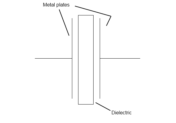
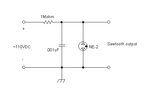
Capacitors store electric charge. They are used with resistors in  timing circuits because it takes time for a capacitor to fill with charge. They are used to smooth varying DC supplies by acting as a reservoir of charge. They are also used in filter circuits because capacitors easily pass AC (changing) signals but they block DC (constant) signals. 

Capacitance

This is a measure of a capacitor's ability to store charge. A large capacitance means that more charge can be stored. Capacitance is measured in farads, symbol F. However 1F is very large, so prefixes are used to show the smaller values.
Three prefixes (multipliers) are used, µ (micro), n (nano) and p (pico):
  • µ means 10-6 (millionth), so 1000000µF = 1F
  • n means 10-9 (thousand-millionth), so 1000nF = 1µF
  • p means 10-12 (million-millionth), so 1000pF = 1nF
Capacitor values can be very difficult to find because there are many types of capacitor with different labelling systems!
There are many types of capacitor but they can be split into two groups, polarised andunpolarised. Each group has its own circuit symbol.

Polarised capacitors (large values, 1µF +)

Examples:   electrolytic capacitors   


electrolytic capacitor symbol

 Circuit symbol:   

Electrolytic Capacitors

Electrolytic capacitors are polarised and they must be connected the correct way round, at least one of their leads will be marked + or -. They are not damaged by heat when soldering.
There are two designs of electrolytic capacitors; axial where the leads are attached to each end (220µF in picture) and radial where both leads are at the same end (10µF in picture). Radial capacitors tend to be a little smaller and they stand upright on the circuit board.
It is easy to find the value of electrolytic capacitors because they are clearly printed with their capacitance and voltage rating. The voltage rating can be quite low (6V for example) and it should always be checked when selecting an electrolytic capacitor. If the project parts list does not specify a voltage, choose a capacitor with a rating which is greater than the project's power supply voltage. 25V is a sensible minimum for most battery circuits.

Tantalum Bead Capacitors

Tantalum bead capacitors are polarised and have low voltage ratings like electrolytic capacitors. They are expensive but very small, so they are used where a large capacitance is needed in a small size.
Modern tantalum bead capacitors are printed with their capacitance, voltage and polarity in full. However older ones use a colour-code system which has two stripes (for the two digits) and a spot of colour for the number of zeros to give the value in µF. The standard colour code is used, but for the spot, grey is used to mean × 0.01 and white means × 0.1 so that values of less than 10µF can be shown. A third colour stripe near the leads shows the voltage (yellow 6.3V, black 10V, green 16V, blue 20V, grey 25V, white 30V, pink 35V). The positive (+) lead is to the right when the spot is facing you: 'when the spot is in sight, the positive is to the right'.

tantalum bead capacitorsFor example:   blue, grey, black spot   means 68µF
For example:   blue, grey, white spot   means 6.8µF
For example:   blue, grey, grey spot   means 0.68µF 

Unpolarised capacitors (small values, up to 1µF)

Examples:   small value capacitors    Circuit symbol:   capacitor symbol

Small value capacitors are unpolarised and may be connected either way round. They are not damaged by heat when soldering, except for one unusual type (polystyrene). They have high voltage ratings of at least 50V, usually 250V or so. It can be difficult to find the values of these small capacitors because there are many types of them and several different labelling systems!
Many small value capacitors have their value printed but without a multiplier, so you need to use experience to work out what the multiplier should be!
For example 0.1 means 0.1µF = 100nF.
100nF capacitor
Sometimes the multiplier is used in place of the decimal point: 


For example:   4n7 means 4.7nF.

Capacitor Number Code

A number code is often used on small capacitors where printing is difficult:1nF capacitor
  • the 1st number is the 1st digit,
  • the 2nd number is the 2nd digit,
  • the 3rd number is the number of zeros to give the capacitance in pF.
  • Ignore any letters - they just indicate tolerance and voltage rating.
For example:   102   means 1000pF = 1nF   (not 102pF!)
For example:   472J means 4700pF = 4.7nF (J means 5% tolerance).
Colour Code
ColourNumber
Black
0
Brown
1
Red
2
Orange
3
Yellow
4
Green
5
Blue
6
Violet
7
Grey
8
White
9

Capacitor Colour Code

A colour code was used on polyester capacitors for many years. It is now obsolete, but of course there are many still around. The colours should be read like the resistor code, the top three colour bands giving the value in pF. Ignore the 4th band (tolerance) and 5th band (voltage rating).10nF and 220nF capacitors
For example:
    brown, black, orange   means 10000pF = 10nF = 0.01µF.
Note that there are no gaps between the colour bands, so 2 identical bands actually appear as a wide band.
For example:
    wide red, yellow   means 220nF = 0.22µF. 

Polystyrene Capacitors

polystyrene capacitorThis type is rarely used now. Their value (in pF) is normally printed without units. Polystyrene capacitors can be damaged by heat when soldering (it melts the polystyrene!) so you should use a heat sink (such as a crocodile clip). Clip the heat sink to the lead between the capacitor and the joint.

Real capacitor values (the E3 and E6 series)

You may have noticed that capacitors are not available with every possible value, for example 22µF and 47µF are readily available, but 25µF and 50µF are not!
Why is this? Imagine that you decided to make capacitors every 10µF giving 10, 20, 30, 40, 50 and so on. That seems fine, but what happens when you reach 1000? It would be pointless to make 1000, 1010, 1020, 1030 and so on because for these values 10 is a very small difference, too small to be noticeable in most circuits and capacitors cannot be made with that accuracy.
To produce a sensible range of capacitor values you need to increase the size of the 'step' as the value increases. The standard capacitor values are based on this idea and they form a series which follows the same pattern for every multiple of ten.
The E3 series (3 values for each multiple of ten)
10, 22, 47, ... then it continues 100, 220, 470, 1000, 2200, 4700, 10000 etc.
Notice how the step size increases as the value increases (values roughly double each time).
The E6 series (6 values for each multiple of ten)
10, 15, 22, 33, 47, 68, ... then it continues 100, 150, 220, 330, 470, 680, 1000 etc.
Notice how this is the E3 series with an extra value in the gaps.
The E3 series is the one most frequently used for capacitors because many types cannot be made with very accurate values.

Variable capacitors

variable capacitor symbol
Variable Capacitor Symbol
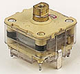
variable capacitor
Variable Capacitor
Variable capacitors are mostly used in radio tuning circuits and they are sometimes called 'tuning capacitors'. They have very small capacitance values, typically between 100pF and 500pF (100pF = 0.0001µF). The type illustrated usually has trimmers built in (for making small adjustments - see below) as well as the main variable capacitor.
Many variable capacitors have very short spindles which are not suitable for the standard knobs used for variable resistors and rotary switches. It would be wise to check that a suitable knob is available before ordering a variable capacitor.
Variable capacitors are not normally used in timing circuits because their capacitance is too small to be practical and the range of values available is very limited. Instead timing circuits use a fixed capacitor and a variable resistor if it is necessary to vary the time period.

Trimmer capacitors

trimmer capacitor symbol
Trimmer Capacitor Symbol
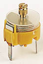
trimmer capacitor
Trimmer Capacitor
Trimmer capacitors (trimmers) are miniature variable capacitors. They are designed to be mounted directly onto the circuit board and adjusted only when the circuit is built.
A small screwdriver or similar tool is required to adjust trimmers. The process of adjusting them requires patience because the presence of your hand and the tool will slightly change the capacitance of the circuit in the region of the trimmer!
Trimmer capacitors are only available with very small capacitances, normally less than 100pF. It is impossible to reduce their capacitance to zero, so they are usually specified by their minimum and maximum values, for example 2-10pF.
Trimmers are the capacitor equivalent of presets which are miniature variable resistors. 

Selasa, 21 Mei 2013

Plasma Capacitor

It came to pass amidst some discussions about a year or so ago on a discussion list I sometimes frequent that the subject of a 'plasma capacitor' came up. What's that? Well, consider the ordinary capacitor, in very simplified form below:
We have two plates, upon which charge is accumulated or placed by some source of electric current, and a dielectric between the plates (in this case, air or vacuum, for simplicity's sake). When the conductive metal plates are charged, an electric field is set up between them, in the dielectric, and electrical energy is stored. This is a simplification, yes, but it's pretty sufficient for what we're going to look into here. The amount of electrical energy stored in the capacitor is given by:
E = 1/2 (C x V^2)
C is the capacitance in farads, V the voltage in volts, and E the energy stored in joules. Assuming a capacitor with a capacitance of 250pF (0.00000000025 farads, something like a 1 foot square pair of plates separated in air by 1/8th inch), and assuming we charge this capacitor to 100 volts, it will store about 1.25 microjoules. In other words, not a whole hell of a lot. But make that capacitor a big Maxwell beast of 10uF, and charge it to 10,000 volts, and you've stored half a kilojoule. That is not a small amount, and if you become the dissipator of said energy, expressed as a transient impulse of some significant power, you may very well die. If you are dead, you probably won't need to read any further, so my suggestion is to go find a nice place (hotel, old warship, etc.) and get busy haunting. If you're alive, continue. If you're undead... well, drop us a line and tell us if Kuru or Creutzfeldt-Jakob is a problem for you guys. Tris notes, "That's just sick."
Fine, we now know how to make a capacitor, which accomplishes very little, because all this has been done before. But let's take a closer look at the simple two-plate capacitor. The plates are usually metal, but can certainly be of some other conductive substance. Saltwater can work, if contained in a bottle with foil wrapped around the outside. The Tesla-coil enthusiasts know this quite well. (At least the ones who didn't switch to 'MMCs.' Come on guys, part of the fun is to make your own stuff Tesla style... storebought caps? Really?)
Carbon could work as a plate material. Even conductive polymers. But what about plasma? Ionized gas. Well, that's what we ended up discussing. As it turned out, from a simple experiment we at United Neko conducted, you can build a capacitor which has one plate made of plasma, and it's rather unsurprising. Plasma is a conductor. But the more we think about it, the more interesting the plasma capacitor starts to look. There might just be some fun things to do here.
Consider this simple circuit:
Many of you will recognize this as the ubiquitous relaxation oscillator. This basic circuit has been used for a number of things, providing a simply derived sawtooth wave from one of the most useful but often overlooked components ever made: the NE-2 neon bulb. Let's consider what happens: when voltage is applied to the above circuit, a charging current flows through the limiting resistor, charging the capacitor and increasing it's voltage. But a funny thing happens when the voltage reaches a certain level; the NE-2 has a breakdown or firing voltage which is less than that of the charging supply. When the capacitor's voltage reaches this threshold, the NE-2 ionizes internally, becoming conductive, and illuminates. This discharges the capacitor, reducing it's voltage. When that voltage falls below what is necessary for the NE-2 to stay lit, it goes out, returning to a nonconducting state. The capacitor begins to charge once more, and the process repeats indefinitely, making a simple oscillator. A photograph of an oscilloscope trace showing this circuit's output is show here:
Why is the circuit important? Well, let's just remove the factory made capacitor "C" from the circuit, and put a would-be plasma capacitor in it's place, and see if it still works. First, however, we must build said plasma capacitor. My muse suggests we need "An enclosed glass vessel, filled with an easily ionizable rarified gas or vapor of some kind, an integral heater-filament to assist in ionizing said gas, and suitable electrodes for contacting and controlling said gas and allowing it to transition to a plasma state!"
. . .
In other words, we can use a fluorescent light bulb. The low pressure gas (usually argon) inside the bulb, and the mercury vapor added (what little the econazis let us have these days) can be ionized and made to conduct electric current, giving off light in the process. This light then impacts and excites a phosphor coating applied to the inside of the bulb, converting the spectrum to something more pleasing and visible to the human eye. Tris likes incandescent's better, but that's just her nature.
So we have a plasma inside this lit tube. That, in theory, should be the first 'plate' of our capacitor. The glass body of the tube will be our dielectric, and a layer of aluminum* foil pasted to the outside of the tube will be the second plate.
*Notice there is only one "I" in 'aluminum'. The poor word must have looked into a laser, and only one "I" remains. So sorry.
Now to make this work as a relaxation oscillator, we need a few isolated power supplies. We need the charging supply for the oscillator; let's make it with batteries. We'll need about 110VDC+, so string a 'bandolier' of 9V transistor radio batteries together. At least where I am, this is very cheap to do; at the dollar store, cheap Panasonic 9V batteries (called 'heavy duty', these are carbon-zinc Leclanche cells) are available in two packs for a dollar. For seven dollars, you can have a 126 volt DC supply that will give a few milliamperes. Don't stick your tongue to it.
We also need a 'keep alive' supply for the fluorescent tube, so that the vapor always stays a reasonably steady plasma. We can do this with wall current. 120VAC mains can be bridge rectified and then smoothed by a filter capacitor of a few hundred microfarads. A disposable camera's photoflash capacitor works well for this, but keep in mind that when charged, it is a dangerous little thing, as is wall current. Don't do this unless you are VERY VERY careful, and as always, we are NOT responsible if you manage to hurt or kill yourself. Do this at your own risk. A current limiting resistor of, say, 10kOhms should be connected in series with the tube to keep from having bad things happen. Tris says: "Yeah, like the tube exploding all over the place! Even though the light and sound show is, like, sooo cool!"
Lastly, we need a "filament" supply for one of the fluorescent tube's heaters. A 6V lantern battery will do just fine. Here is a schematic depicting how I wired everything together, and below that, a photograph of it in practice.
Now we can turn on everything, at which point, nothing will happen; we need a source of a fast high voltage pulse to get the tube ionized enough for it to switch on begin conducting current. A piezoelectric striker commonly used as an igniter for propane barbecue grills can be used. I purchased mine from a local hardware store, as my muse would likely strangle me for disabling a BBQ. It's also possible to 'cannibalize' them from old, derelict BBQ grills that are thrown away as unsafe to use. The piezo striker doesn't commonly fail. To ignite the tube, it's a simple matter of applying power from all the supplies, making sure the filament is running (you should see an orange glow from it if the room is momentarily darkened), and clicking the piezo striker when held near the tube. If done properly, the tube will immediately light. Sometimes you might have to click one or two times. The running apparatus, with the gas ionized, is shown below.
But does it work as a plasma capacitor? Does the relaxation oscillator work?
It does, and quite well. As there is no other capacitor in the circuit, the only conclusion we can come to is that the tube is indeed functioning as a capacitor with a single metal plate, and an ionized gas 'plate.' As can be seen, the sawtooth isn't the cleanest waveform. It is rich in odd content, not at all smooth, but it is at least clear what it is. From the above, and from playing around with the setup, it seems as if the sawtooth wave begins its logarithmic rise, is interrupted and even discharges to some degree, with other content appearing in the waveform, then eventually continues its rise, peaks, and discharges. What causes this nonlinear charging waveform? One would assume it is generated in the plasma side of the 'capacitor', and not the foil. Plasmas are known for having 'negative resistance' characteristics under some circumstances. Is that what is happening here?
Calculating the capacitance of the tube is not as simple as it would first seem, at least in this setup. The relaxation oscillator frequency is determined by the values of R and C in the circuit. We could assume R ~ 1Mohm, as the charging resistor is, and solve for C, but there lies the question of how conductive the plasma is. If it has a high resistance value, at least in some part of the charging cycle, the frequency will be changed, and we cannot derive an exact value for C. Off the cuff measurements, matching a known capacitor to the frequency of the oscillator, give a value of somewhere around 0.001uF for the tube and foil used. The tube is manufactured by General Electric, type F15T8-CW.
Another interesting, and perhaps useful effect is illustrated by the waveform below. Pulses of sawtooth relaxation impulses are shown.
What's interesting about this? How it was produced; the smoothing capacitor across the bridge rectifier feeding the tube's plasma was eliminated. Instead of the plasma being continuously 'lit' by smooth DC, it was now pulsing at 120cps. The sawtooth pulse trains above come in groups of about 5, 120 times per second. If we used half-wave rectified AC, the pulses would only come 60 times per second, and would be separated by a greater time of quiescence. What can we do with this? Well, one wonders if we could use this 'switching capacitor' to make a radio transmitter. Assuming a relaxation oscillator could be made to work with this or a similar setup at RF, if we could modulate the plasma 'keep alive' current at audio, can we send low power CW?
Also, when the plasma 'keep alive' current is reduced, and the tube dims, the relaxation oscillator frequency changes. By modulating the current in this manner, could we make a plasma FM modulator?
One last thing; thinking back to the well known formula E = 1/2 (C x V^2), can we get the capacitive analogue of inductive kickback? When we have a high-value inductor connected to a low voltage current source, and suddenly interrupt the current flow, the collapsing magnetic field induces a very high voltage. This is how automotive ignition coils function, and is pretty well understood. But can we do the same thing, but capacitively, with the 'plasma capacitor'? If we have a capacitance of value C, charged to some voltage V, and we suddenly 'kill' the capacitance by drastically reducing one plate very fast (we 'unlight' the plasma), what happens? E must remain constant; so it would seem that if the capacitance were reduced, V would rise to a high value. Assuming a capacitor of .001uF, as above, charged to say, 500V, we get a stored energy of 0.125mJ. If we suddenly reduce C to 1% of its initial value, or 10pF, assuming E remains constant, with little lost to heat or something else, V would seem to increase to 5000 volts (!). Does it actually work, or is something being missed?
My muse suggests "Additional experimentation is required!" I'd be inclined to agree.

Polarised capacitors (large values, 1µF +)


Examples:   electrolytic capacitors    Circuit symbol:   electrolytic capacitor symbol

Electrolytic Capacitors

Electrolytic capacitors are polarised and they must be connected the correct way round, at least one of their leads will be marked + or -. They are not damaged by heat when soldering.
There are two designs of electrolytic capacitors; axial where the leads are attached to each end (220µF in picture) and radial where both leads are at the same end (10µF in picture). Radial capacitors tend to be a little smaller and they stand upright on the circuit board.
It is easy to find the value of electrolytic capacitors because they are clearly printed with their capacitance and voltage rating. The voltage rating can be quite low (6V for example) and it should always be checked when selecting an electrolytic capacitor. If the project parts list does not specify a voltage, choose a capacitor with a rating which is greater than the project's power supply voltage. 25V is a sensible minimum for most battery circuits.

Smoothing


Smoothing is performed by a large value electrolytic capacitor connected across the DC supply to act as a reservoir, supplying current to the output when the varying DC voltage from the rectifier is falling. The diagram shows the unsmoothed varying DC (dotted line) and the smoothed DC (solid line). The capacitor charges quickly near the peak of the varying DC, and then discharges as it supplies current to the output. 


Smoothing 
Note that smoothing significantly increases the average DC voltage to almost the peak value (1.4 × RMSvalue). For example 6V RMS AC is rectified to full wave DC of about 4.6V RMS (1.4V is lost in the bridge rectifier), with smoothing this increases to almost the peak value giving 1.4 × 4.6 = 6.4V smooth DC.
Smoothing is not perfect due to the capacitor voltage falling a little as it discharges, giving a small ripple voltage. For many circuits a ripple which is 10% of the supply voltage is satisfactory and the equation below gives the required value for the smoothing capacitor. A larger capacitor will give less ripple. The capacitor value must be doubled when smoothing half-wave DC.
There is more information
about smoothing on the
powersupplyschematics.blogspot.com/
website.
 Smoothing capacitor for 10% ripple, C =5 × Io   
Vs × f
C  = smoothing capacitance in farads (F)
Io  = output current from the supply in amps (A)
Vs = supply voltage in volts (V), this is the peak value of the unsmoothed DC
f    = frequency of the AC supply in hertz (Hz), 50Hz in the UK
 

Transformer + Rectifier + Smoothing + Regulator


Regulated DC power supply, transformer + rectifier + smoothing + regulator 
The regulated DC output is very smooth with no ripple. It is suitable for all electronic circuits.

Further information: Transformer | Rectifier | Smoothing | Regulator

Transformer + Rectifier + Smoothing


Smooth DC power supply, transformer + rectifier + smoothing 

The smooth DC output has a small ripple. It is suitable for most electronic circuits.
Further information: Transformer | Rectifier | Smoothing