 |  |
| Voltage regulator Photograph |
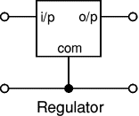
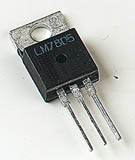
Many of the fixed voltage regulator ICs have 3 leads and look like power transistors, such as the 7805 +5V 1A regulator shown on the right. They include a hole for attaching a heatsink if necessary.
Please see the Electronics in Meccano website for more information about voltage regulator ICs.
| zener diode a = anode, k = cathode |
 |
Zener diode regulator
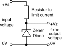
For low current power supplies a simple voltage regulator can be made with a resistor and a zener diode connected in reverse as shown in the diagram. Zener diodes are rated by their breakdown voltage Vz andmaximum power Pz (typically 400mW or 1.3W).
The resistor limits the current (like an LED resistor). The current through the resistor is constant, so when there is no output current all the current flows through the zener diode and its power rating Pz must be large enough to withstand this.
Please see the Diodes page for more information about zener diodes.
Choosing a zener diode and resistor:
- The zener voltage Vz is the output voltage required
- The input voltage Vs must be a few volts greater than Vz
(this is to allow for small fluctuations in Vs due to ripple) - The maximum current Imax is the output current required plus 10%
- The zener power Pz is determined by the maximum current: Pz > Vz × Imax
- The resistor resistance: R = (Vs - Vz) / Imax
- The resistor power rating: P > (Vs - Vz) × Imax
Vz = 4.7V (nearest value available)- Vs = 8V (it must be a few volts greater than Vz)
- Imax = 66mA (output current plus 10%)
- Pz > 4.7V × 66mA = 310mW, choose Pz = 400mW
- R = (8V - 4.7V) / 66mA = 0.05k
 = 50
= 50 , choose R = 47
- Resistor power rating P > (8V - 4.7V) × 66mA = 218mW, choose P = 0.5W


Tiada ulasan:
Catat Ulasan
Pls given your comment to improve my blog